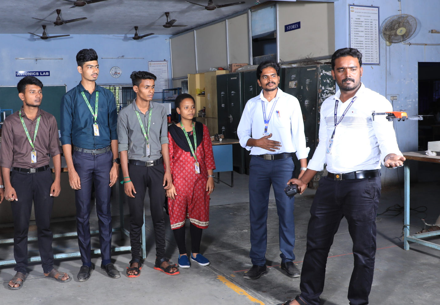
The Department of Aeronautical Engineering is equipped contemporary Laboratory & Testing facilities like Aerodynamics Lab, Propulsion Lab, Aircraft Structures Lab, CAD Lab, Aircraft Design Project Lab, Flight Training/ Flight Simulation Lab, Aero Engine & Airframe Lab and Aircraft Systems Lab as per Anna University Regulation 2021
OBJECTIVES:
OUTCOMES:
The Students will be able
The Aerodynamics Lab has been provided with experimental facilities such as;
Two numbers of low speed wind tunnel with a test section size of 2’X2’ is available in the aerodynamics lab. It can be best used for flow visualization studies, pressure measurements and force measurements for aerospace bodies flying at low velocities up to 50m/s.
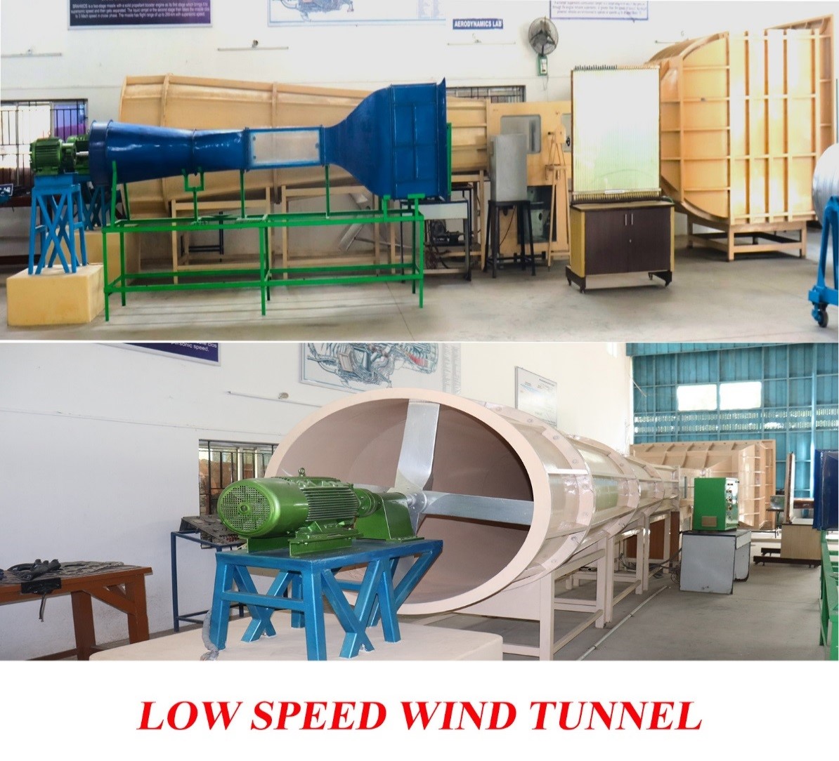
The facilities of Laser Smoke Flow Visualization, Pressure Scanner and Internal Six Component Strain Gauge Balance were beyond the scope of B.E. Anna University syllabus and intended only for Research.
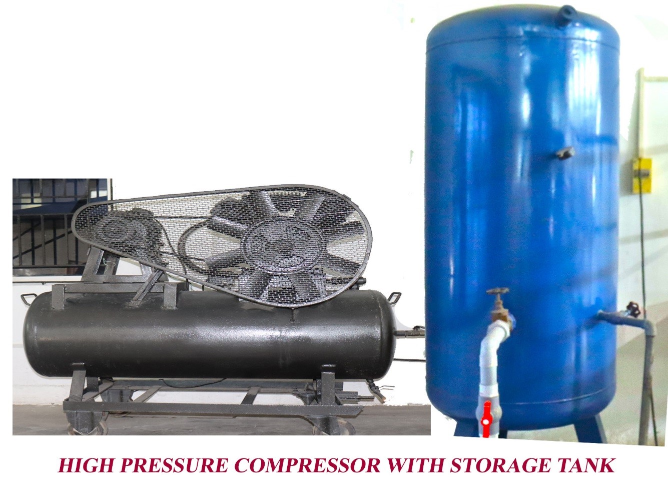
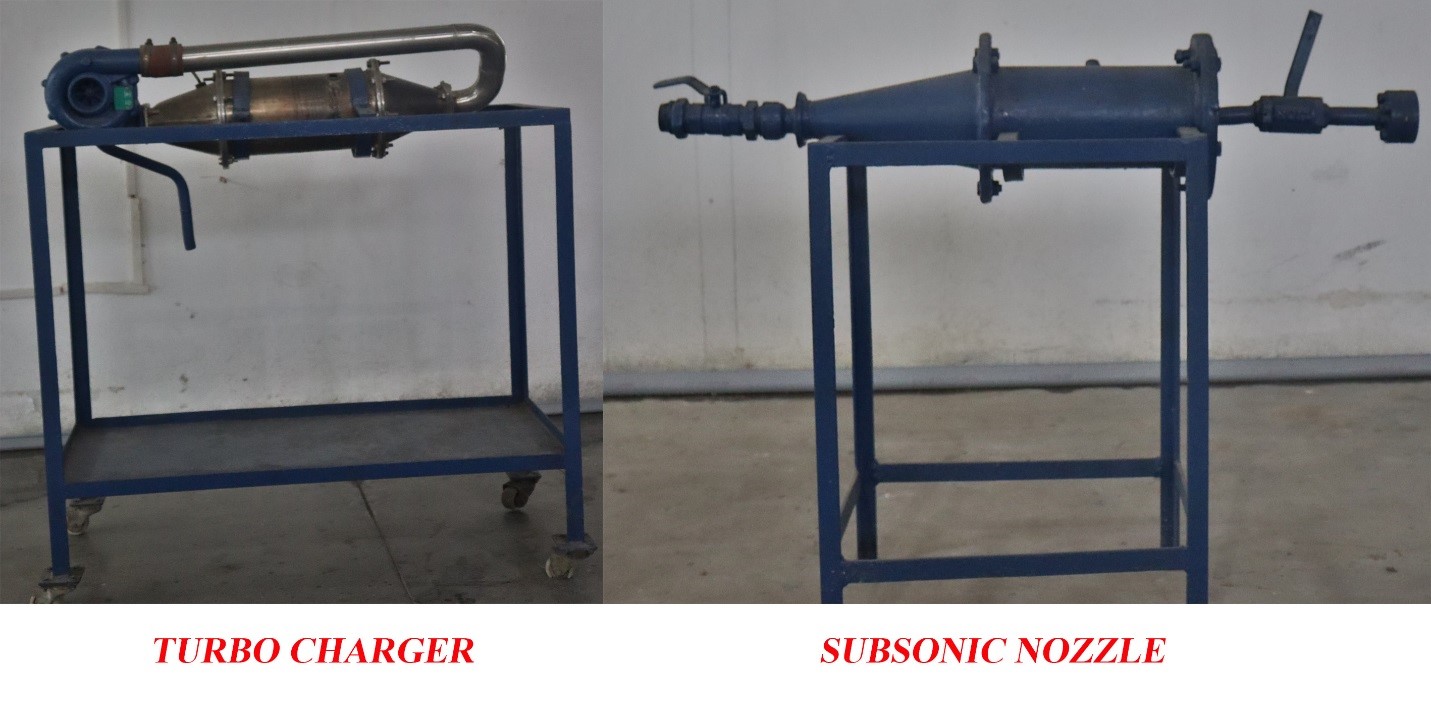
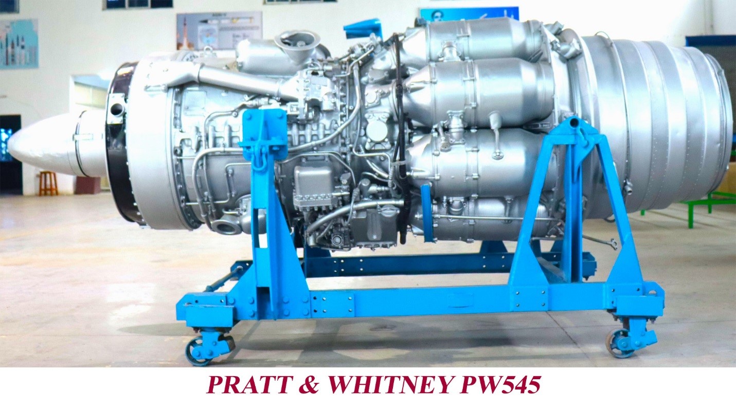
The main purpose of the compressor is to supply compressed air for fuel pressurization and injection into the engine.
Specification of the Compressor
OBJECTIVES:
OUTCOMES:
The Students will be able to:
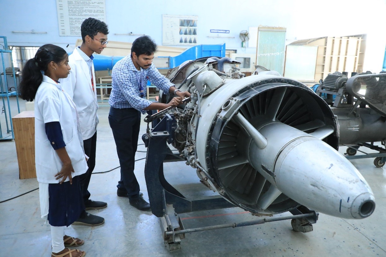
The list of equipment in propulsion lab includes;
A Bomb calorimeter is an object used for calorimetry, or the process of measuring the heat of chemical reactions or physical changes as well as heat capacity. Differential scanning calorimeters, isothermal micro calorimeters, titration calorimeters and accelerated rate calorimeters are among the most common types. A simple calorimeter just consists of a thermometer attached to a metal container full of water suspended above a combustion chamber.
This facility is dedicated to conducting experiments and studies related to High-speed internal flows and Jet dynamics. The capability to achieve Mach numbers from subsonic to high supersonic suggests that the facility is equipped to simulate a wide range of Aerodynamic conditions.
Such facilities are crucial for research in Aeronautical/Aerospace engineering, particularly for understanding the behavior of airflows in propulsion systems, Jet engines, and other high-speed applications. Researchers and Engineers can use these facilities to test and validate theories, as well as to optimize designs for efficiency and performance.
OBJECTIVES:
OUTCOMES:
The Students will be able to:
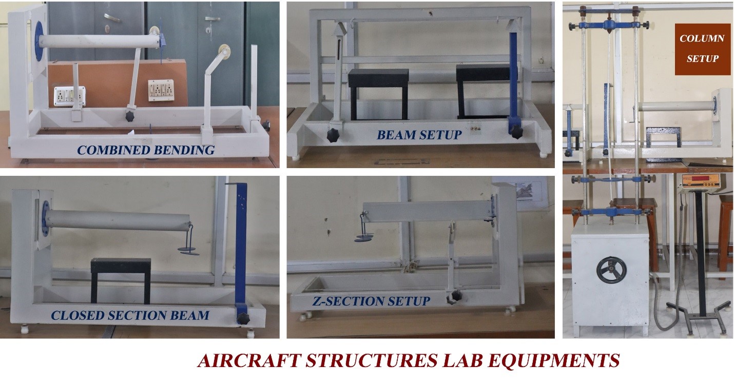
Photo-elasticity is an experimental method to determine the stress distribution in a material. The method is mostly used in cases where mathematical methods become quite cumbersome. Unlike the analytical methods of stress determination, photo-elasticity gives a fairly accurate picture of stress distribution, even around abrupt discontinuities in materials. The method is an important tool for determining critical stress points in a material, and is used for determining stress concentration in irregular geometries, for this we use a equipment called Polariscope.
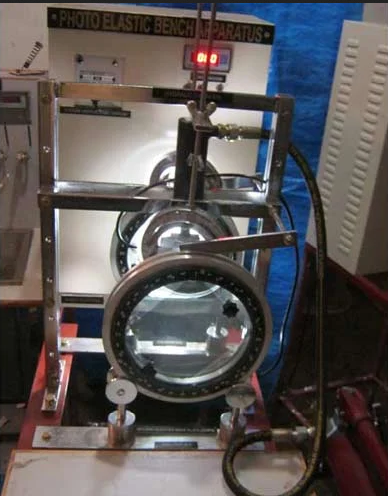
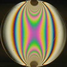
Principle of Polariscope
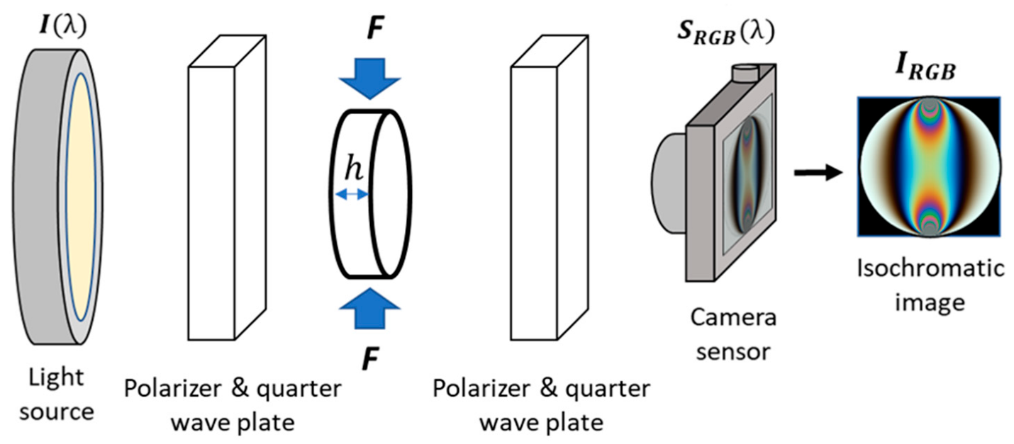
Isochromatic fringe patterns around a steel platelet in a photo-elastic two-part epoxy resin.

Coloumn Test Apparatus
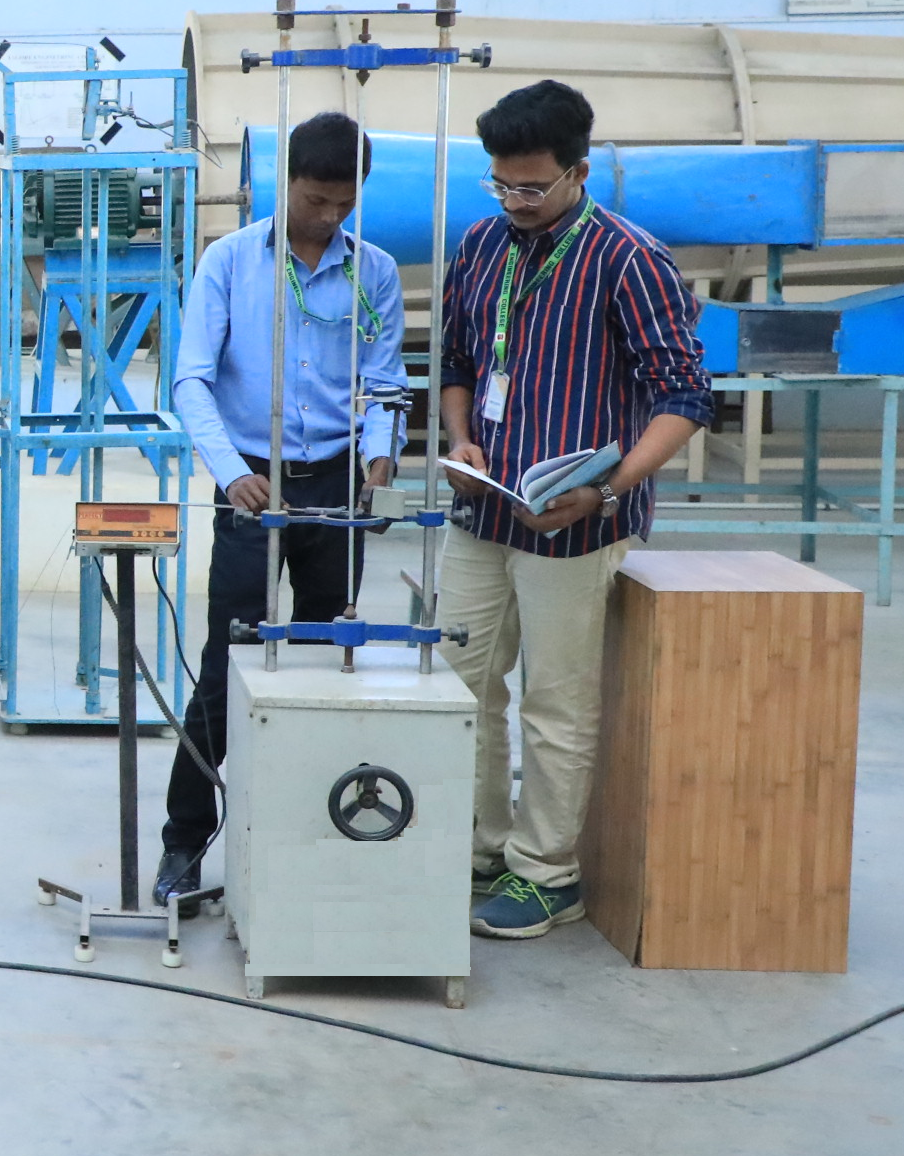
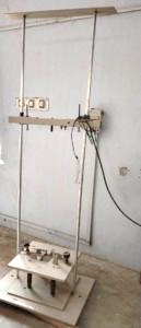
Drop Weight Impact Testing Machine
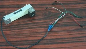
Drop Weight ImpactTesting Machine with Load Cell
Composite laminates are prepared and their Impact Strength is tested using this facility. Up on connecting this machine with DAS time dependent Impact Strength of materials can be obtained.
OBJECTIVES:
OUTCOMES:
The Students will be able to:
OBJECTIVES:
OUTCOMES:
The Students will be able to:
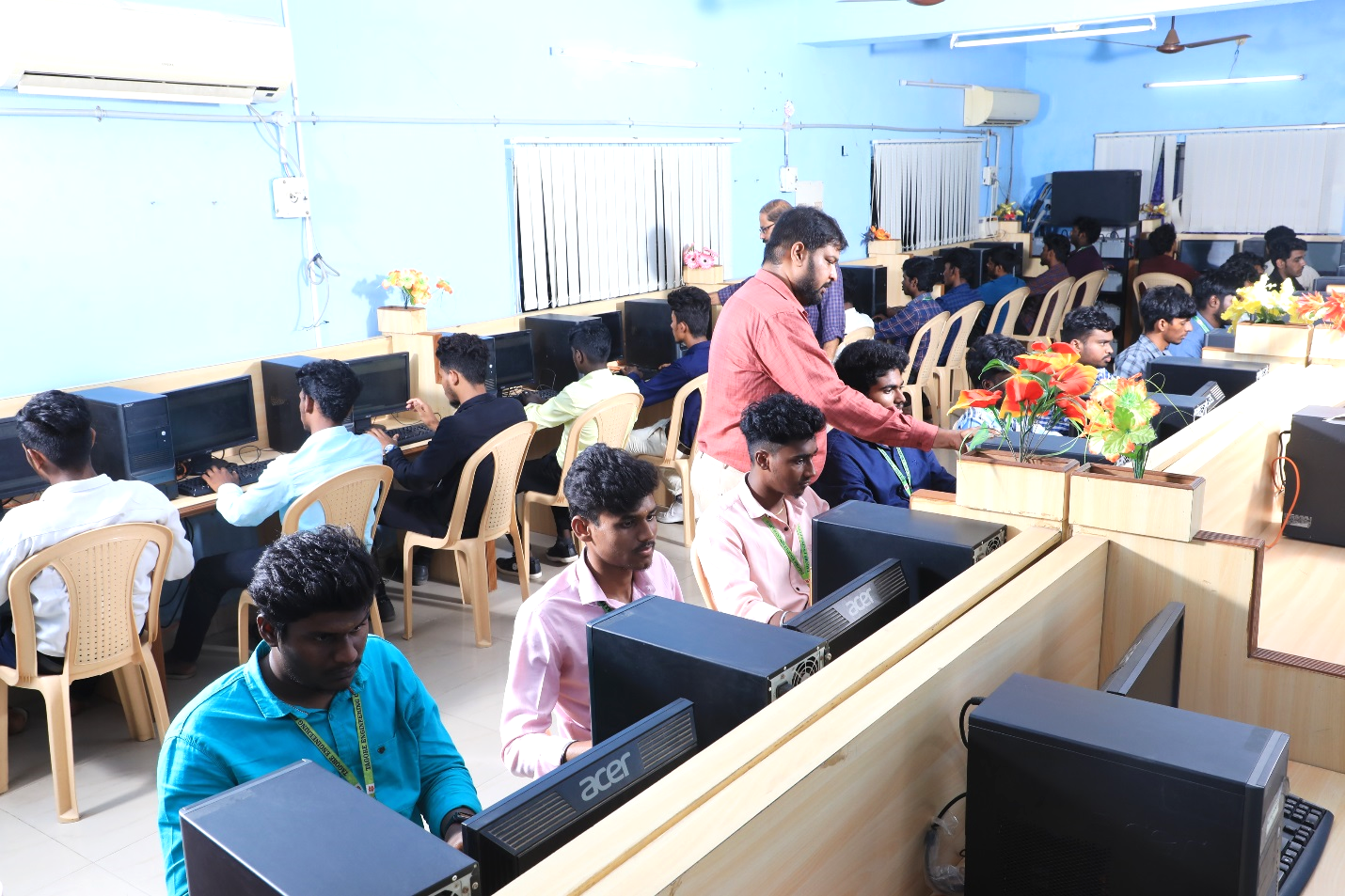
The Aeronautical Engineering Department has been provided with about 30 no’s of computers with updated configurations and also high speed Internet Facility. Software for Design, Stress Analysis and Flow Analysis along with Microsoft office Mathematical packages are available. This facility is dedicated to various Labs like CAD Lab, Aircraft Design Project and Computational Analysis Lab.
OBJECTIVES:
OUTCOMES:
The Students will be able to:
OBJECTIVES:
OUTCOMES:
Upon completion of the Aircraft Design Project students will able to
OBJECTIVES:
To familiarize with
OUTCOMES:
On successful completion of this course, the student will be able to
COURSE OBJECTIVES:
Of this course are